
Let’s take a closer look at how a dimmer switch works
Wondering how a dimmer switch works?
A light dimmer switch is a device that helps to control the level of light output from a light source. By altering the amount of power delivered to the light source, the dimmer switch can directly affect the level of light output.
The more power that is delivered, the higher the light output will be.
Conversely, the less power that is delivered, the lower the light output will be. In this way, a dimmer switch can be used to create different levels of lighting, depending on the needs of the situation.
Whether you are looking for a soft glow to set the mood or a bright light to help you get things done, a dimmer switch can help you get the perfect level of lighting for any situation.
- By altering the amount of power delivered to a light source, a dimmer directly affects the level of the light output from that source.
- The more power delivered, the higher the light output. The less power delivered, the lower the light output.

On-Off Switch
The two extremes of the light output range are of course achievable by a simple switch.
With a simple switch, we either turn the light on, meaning we close the circuit, delivering full power to achieve the full light output capabilities of the lighting mode, or turn the light off.
Meaning we open the circuit, cutting off power from the lighting load and getting no light output in return.
While this explanation is obvious and straightforward, the concept is actually foundational to the understanding of how typical dimmers work.

In order to achieve light level from are given lighting load, that is somewhere between fully bright and fully off, what the dimmer actually is doing a switching power on and off at a high rate of switching. Thereby reducing the power delivered to the lighting load and resulting in a lower light output.
- With a simple switch, we can either turn the light on or turn the light off. This is because a simple switch closes or opens the circuit, respectively cutting power to the lighting load. To achieve light levels between fully bright and fully off, a dimmer switches power on and off at a high rate of switching, thereby reducing the power delivered to the load.
High-Frequency Switch
The frequency of the switching is high enough that you cannot see it.
The very nature of the power delivered by the electric company makes this feasible.

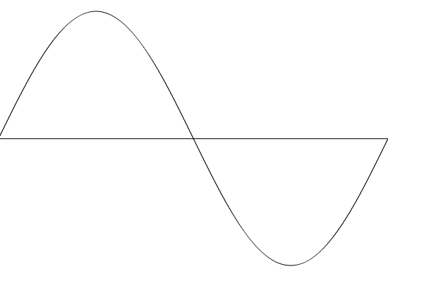
This graphic represents a single cycle that delivered a sinusoidal voltage signal. This cycle repeats 60 times every second.
Using a simple light switch and turning that switch on, we will be delivering this voltage to the lighting load throughout the entire cycle.
As a result, the current would flow through the lighting load.
The product of the voltage applied and the resulting current through the lighting load to determine the power delivered to the lighting load.

To reduce the light level output again, we need to reduce the amount of power that’s delivered. We will do so by switching twice,
off and on during a cycle. Using power electronics, such as a triac, we can turn the voltage off, where the sine wave crosses the zero line. Then we leave it off for a certain delay, then back on in order to deliver some power, and reduce power to the load.
And we do that again on the negative side. The longer the delay before turning on, the less power we will be delivering, and the lower the light level of the light source.
Forward Phase Dimmer
So this then would be the modified waveform coming out of the forward phase dimmer. So this is how a standard dimmer works.
A dimmer with the output characteristics explained here, is known by many names, including standard dimmer, household dimmer, incandescent dimmer, Triac dimmer, magnetic dimmer, forward phase dimmer, and leading-edge dimmer. I will refer to this throughout the remainder of the article as a forward phase dimmer.
Keep in mind that these dimmers were developed for dimming conventional light sources, particularly incandescent lamps.
Resistive light sources
These light sources are resistive in nature and they don’t care about the shape of the wave applied. They will react to how much power is delivered to them, regardless of the waveform.
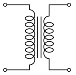
When the lamp is low voltage and a transformer is used to convert the line voltage to 12 volts, for example, to apply to that lamp, then the addition to the lamp itself, some complexity is introduced by the transformer.
Now conventional wire rounded magnetic transformers are compatible with this type of dimming or forward phase dimming,
so long as certain factors are implemented in the dimmer.
For example:
The power delivered during the positive half of the cycle must equal the power delivered during the negative cycle. So that any DC component the power delivered is within the tolerance of transformers, and out of tolerance, DC component would cause the transformer to saturate, leading potentially to its failure.
Incandescent dimmer vs magnetic dimmer
So the difference between an incandescent-rated dimmer and a magnetic-rated dimmer is the ladder’s ability to perform without detriment to the transformer -they are both forward phase dimmers.
Electronic dimmer switch
At one point in the history of light source development, the electronic transformer was introduced, with a very different set of characteristics from those of a magnetic transformer.
One key difference is that it is not all compatible with a sudden voltage rise, which occurs twice during each cycle.
So there’s a compatibility issue between the electronic transformer and the standard dimmer – you cannot use the two together.
The solution to dimming electronic transformers is, to swap the sequence of power delivery to the lighting load each half-cycle, instead of opening the switch at the beginning of the cycle, the switch is closed and at that point, the power is delivered for a time.
Then after a predetermined delay, the voltage is turned off and power is no longer delivered for the remainder of the half-cycle.
In this way, no sudden voltage rises occur, so it works with the electronic transformer.
ELV or electronic voltage dimmer
Dimmers that produced this backward waveform, are more known by the following terms: elv or electronic low voltage dimmer, simply electronic dimmer, reverse-phase dimmer, or trailing edge dimmer.
I will refer to these from here on out as reverse phase dimmers.
Again the incandescent light source, without a transformer doesn’t care about the waveform. So we can then dim line voltage incandescents with either forward Phase or reverse-phase dimmers.
However, the following differences exist.
The triac that is used to perform forward Phase dimming, cannot be operated in the reverse-phase matter and so different electronics are used for reversed-phase dimming – typically a FET or an IGBT.
These electronics are comparable more expensive than a triac and their current ratings are typically lower. So if you use reverse phase dimming you will pay a premium and your load capacity will be somewhat lower, compared to the forward phase dimmer.
Compatible dimmer switches
I should mention here, that some electronic low voltage transformers have been modified, specifically to be compatible with forward phase dimmers.
The manufacturer of the elv transformer must state, that it is compatible with forward phase dimmers or an electronic transformer should always be paired with a reverse-phase dimmer.
As these two introduced dimming methods share a common concept, of switching power on and off during each half-cycle, and because they’re not the only means of dimming, we’re going to classify them together and refer to them collectively as phase counter phase control dimming.
While phase control is still the primary dimming method, it is not the only method. Historically there came the point when it became desirable to dim fluorescent light sources, but fluorescent lights don’t typically respond well to phase control dimmers.
So other methods of dimming became commercially available.
All of which have carried forward in one form or another to LED dimming.
These other methods of dimming differ from phase control dimmers, in that the dimmer is not actually directly modifying the power delivered to the lighting’s load.
Rather it’s sending a signal, a control signal to an intermediary electronic circuit, known as a dimmable ballast in the fluorescent fixture or a dimmable driver in an LED fixture.
Indirect dimmer switches
The signal is used to communicate to what level the light output should be set and the ballast driver uses some mechanism beyond the scope of this article, to achieve that lighting level. For this reason, I refer to dimmers that use these methods as indirect dimmers.
Indirect dimmers are of two major types: analog and digital.
I will discuss the analog indirect dimmers first.
A light source that includes indirect dimming capability will be looking for a variable control signal, separate from the power delivered, that power typically being switched on and off by the controlling dimmer, in addition to the variable control signal.
The first type of control signal I will discuss is the variable low voltage output – sometimes referred to as zero to ten dimming.
Such a device will react to a control signal, that varies between 0 and 10 volts DC, to regulate the light output.
If the control signal received is 10 volts, the device causes the light output, to go to its full-on value.
If the control signal received is zero volts, the device causes the light output to go to its minimum or off value.
A control signal value of 5 volts, being at the midpoint of the control signal range would cause the light output, theoretically to go to the fifty percent output level.
The second method of analog indirect dimming is pulse width modulation or PWM.
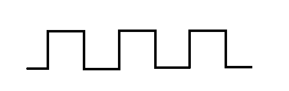
In PWM a constant voltage square wave is a repeating square wave as a control signal.
Now the percentage of the time that the voltage is on, is actually the variable.
We don’t change the frequency, we don’t change the voltage, we just change the duration, then it is on. And that goes between 0 and 100 percent.

Now there is a standard that applies to dimming pulse width modulated control light sources.
That standard is actually the opposite of what you might expect. Meaning that if I were to actually apply zero percent of the time
voltage, then the light output is actually going to be a hundred percent and reduce down linearly to 0 percent when we apply a hundred percent of the time the voltage – opposite of what you expect.
Now because it is the opposite of what we expect, you do find from time to time manufacturers of PWM control light sources that don’t comply and go more with what you would expect.
With those light sources, if I apply the voltage zero percent of the time, then I will get 0 light output.
And I will increase linearly up to a hundred percent or full output when I get a hundred percent of the time that I’m applying voltage.
A third and final method of analog indirect dimming uses a line voltage phase control waveform as a control signal.
Such a device is characterized by a neutral conductor, a conductor for power switching, and a conductor for dimming control.
So it’s known as a three-wire baluster – a three-wire driver.
While the power delivered to the light sources switches between the switch leg and neutral, in addition, a face control signal is applied between the third conductor neutral, to signal the desired light output level.
Finally, there is indirect digital dimming, wherein we will send a series of bits, according to a preset protocol to communicate commands and status updates over a two serial communication port.

Two examples of this are DMX and Dali while these technologies are mentioned to round out the discussion of dimming control, they fall outside of the scope of this article.
I hope you understand a little bit more about dimming now.
Led lights can be dimmed using any methods discussed in this article.
That`s pretty much how a dimmer switch works.
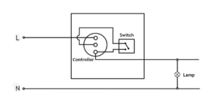
Dimmer switch circuit diagram
FAQ
Does a dimmer switch reduce voltage?
It works by changing the voltage waveform applied to the lamp, it is possible to lower the intensity of the light output.
How do old dimmer switches work?
Old dimmer switches had a rather straightforward resolution for adjusting light levels.
A variable resistor, a regular resistor is a bit of material that doesn’t conduct electrical current great. It gives a lot of resistance to moving electrical charges. A variable resistor consists of a lot of resistive substances, a stationary contact arm, and a moving contact arm.
You alter the total resistance of the resistor by adjusting the distance that the charge has to go through a resistive material. If the contact arm is to the left, the charge running through the circuit simply has to travel through a little bit of resistive material. If the contact arm is all the way to the right, the charge has to pass through a more resistive material.
As the charge goes to move through the resistor, energy is dissipated in the form of heat. And when you put a resistor in a series circuit, the resistor’s energy consumption makes a voltage drop in the circuit, decreasing the energy available to light bulbs. And the decreased voltage across the light bulb decreases its light output.
Dimmers provide a way to lower the brightness of a light, which can be helpful when trying to create a specific mood or effect. They can also help to save energy, as they allow for more precise control over the amount of light that is emitted. While there are some drawbacks to using dimmers – including potential flickering and humming – they remain a popular choice for controlling light fixtures.
I hope this article helped you understand how a dimmer switch works. Thank you for reading.